AE ARCHITECTENGINEER ADDNL ADDITIONAL B BOTTOM BO. Spacing mm if required.
Reading Structural Drawings 1 Youtube
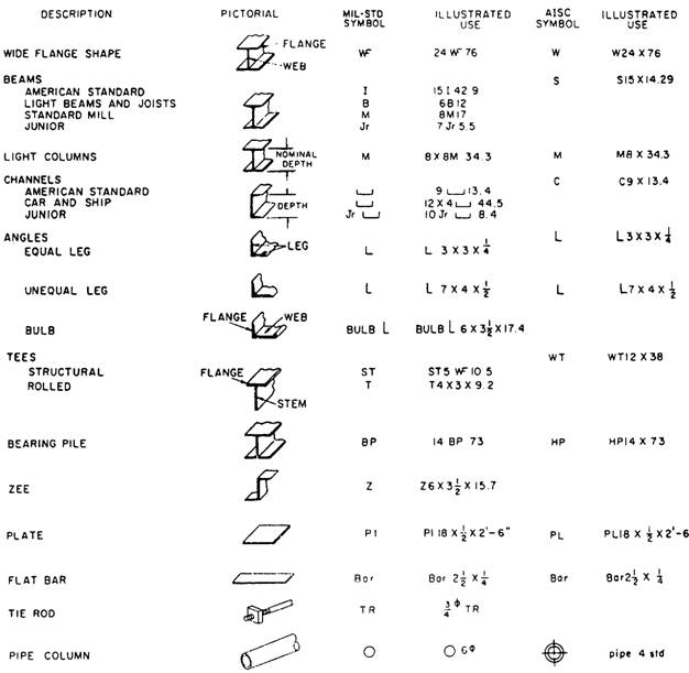
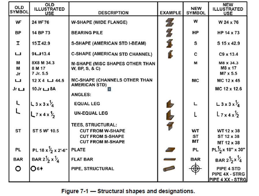
A structural tee is made by slitting a standard I- or H- beam through the center of its web thus forming two T-shapes from each beam.

. Structural Plan Symbols. Each structural engineering office uses their own set of plan symbols. Concerning welDing anD suBsequenT Touch-up oF galvanizeD sTeel is availaBle in The american galvanizers associaTions aga Welding Hot-dip galvanizing puBlicaTion.
Old Designation for Tube Steel no longer. Thickness of Shape NON Standard AISC Call Out. 267 rows There is only one correct casing for the symbol cap-M-cap-P-small-a which like any SI unit of measurement symbol properly should be preserved even when surrounding text is styled in all caps which latter is a frequently employed tradition in engineering drawing.
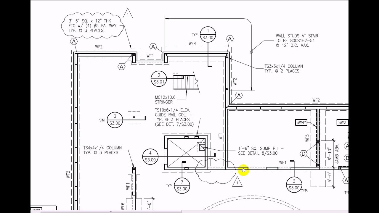
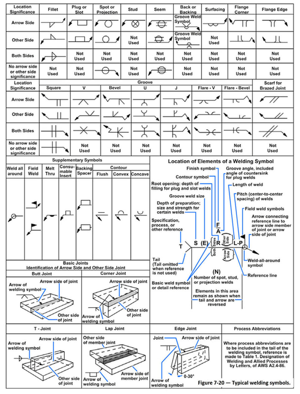
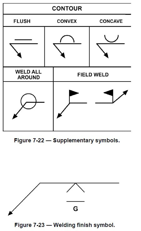
Essentially a structural steel drawing shows the position of each structural steel material used in the building. Symbols Commonly Used in Structural Drawings Strength. See Figure 4 for specifying weld length and location.
When starting out reading structura. Symbols and abbreviations for concrete as per aci general existing construction north 1 sd package - 03-30-11 5 symbol legend structural abbreviations s210 foundation plan s501 foundation details s502 steel details s220 roof framing plan dd package - 04-08-11 5 s503 6 permit - 04-22-11 revisions - 06-06-11 3 steel stud details 7 permit review - 06-27-11. Many Structural Engineering detail drawings are read using the Architects scale.
Blueprint Symbols are generally used to indicate function objects or systems in the floor plan or any kind of engineering drawing. Ie a permanent steel pan formwork for a suspended concrete slab. HSS Fy42ksi TS Fy42ksi Standard AISC Call Out.
The plans sequences and required materials are predetermined. Structural symbols and legend moment connection north arrow span direction section detail mark elevation mark recess or step in slab plan detail mark plan note column grid line column and foundation type marks sloped surface pitched roof tilt-upprecast concrete wall wall types sf. 2-0 roof joist beam roof joist step foundation step height detail number.
BOTTOM OF BLDG BUILDING CL. The scale of a drawing is usually presented as a ratio and is read as illustrated in the following examples. This will guide contractors while they pick out materials for the building.
Architects Scales and Sizes 16 Scale Full Size 12 1- 0. It could be present in structural drawing architectural drawing electrical drawing machine etc. Structural grid indicator structural grid line 1 2 b a revision area revision number symbol 1 1 base plate mark spot footing mark symbol 1 f1 bp1 spot footing mark base plate mark cf1 continuous footing mark wall mark symbol w1 wall mark 0 4 8 16 0 4 8 16 sideplate moment connection symbol see sideplate drawings ae architectengineer ab anchor bolt aban abandon.
IF possiBle sTeelwork shoulD Be DesigneD To Be BolTeD raTher Than welDeD aFTer galvanizing. For example the symbol ST 5 WF 105 means the tee has a nominal depth of 5 inches a wide flange and weighs 105 pounds per linear foot. CJP S E S E A A E S A S E E E S E S E A.
WelDing symBols are Those DeFineD in aws a24-2012 Welding. A structural steel drawing has some key components. Bar notation gives the following information in this ordernumber of bars.
We also have another article that can help you identify structural abbreviations used in a drawing set. DIMENSION DWG DRAWING EF. CJP PJP fillet flare-bevel If joint or connection has a required strength defined by the SER sizes are not necessary on structural drawings.
Ad Structural Steel Detailing Company - Columns Beams Stairs Railings. But it is not uncommon to see MPA through carelessness. Aside from the simple length markings there are many other symbols that can be seen on structural steel fabrication drawings depending on the type of assembly and material.
Depth in Long Direction 5. Learning the symbols meaning on steel structure drawings plays a critical role in reading the drawing. 1 1 Read as 1 inch on the drawing equals 1 inch on the actual component or system.
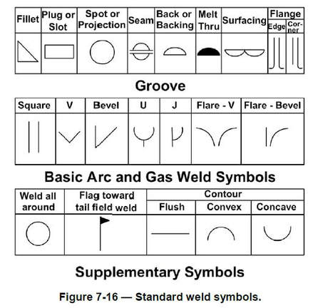
However the symbols below are fairly standard at many offices. Common Weld Symbols Weld Type Structural Drawings Show. Structural steel is fabricated or erected a plan of action and sequence of events be set up.
Architects scale always reads X 1- 0 For example ½ 1- 0 or 3 1- 0. Width in Short Direction 58. This is a drawing that shows the connections of the steel materials used in construction.
This can also be stated as FULL SIZE in the scale block of the drawing. Grade of steel used for rcc works shall be fe500tmt. It is important to know How to read Structural Steel Drawings and it isnt something that is covered during university.
Lap reinforcement only at locations shown in the drawings. Types of Blueprint Symbols. For example symbols representing sections or heights common signs include circles rectangles triangles etc.
Reinforcement is represented diagramatically and not necessarily in true projection. For example you can use this to show the span direction of Bondek Condek Kingspan etc. Hollow Structural Shape 9.
Refer to the symbol legend sheet for special symbols used in a particular set. In dimensioning the structural tee symbol is preceded by the letters ST. The measured distance on the drawing is the actual distance or size of the.
GENERAL NOTES ABBREVIATIONS SYMBOLS LEGEND. CENTER LINE CMU CONCRETE MASONRY UNIT CONC. A useful AutoCAD block for structural drafting.
A span direction symbol for a structural element. This for example is an angle symbol showing under what angle should two pieces be merged.
Structural Steel Drawings
Structural Steel Drawings
Chapter 7 Structural And Architectural Drawings

Pin On Civil Engineering
Structural Steel Drawings
Structural Plan Symbols Archtoolbox

How To Read Structural Steel Drawings Directorsteelstructure
Structural Steel Drawings
0 comments
Post a Comment